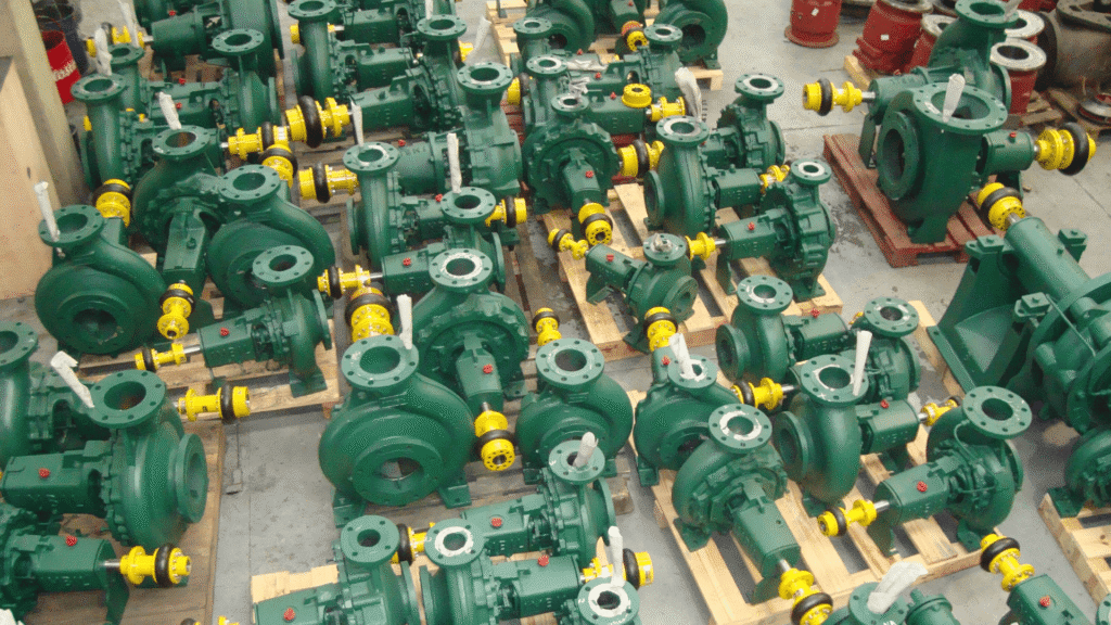
Use of AT Coupling on Belt Conveyors
Do you know the importance of coupling in belt conveyors? Some industrial systems require a most rigorous performance and, therefore, selecting the right components is essential, ensuring the efficiency, durability and safety of the equipment. In this sense, when we talk about belt conveyors, one of the critical elements is the coupling between the motor and the reducer. The AT coupling stands out as a superior technical choice, offering multiple benefits.
However, there are several coupling alternatives that can be used in this application, each with specific characteristics for different situations and operational requirements. See more information below!
Gear Couplings
Gear couplings are robust and capable of transmitting high torques. They consist of two halves with teeth that mesh, allowing a certain degree of misalignment. Therefore, these couplings are ideal for applications where heavy loads are expected and where alignment accuracy is not critical.
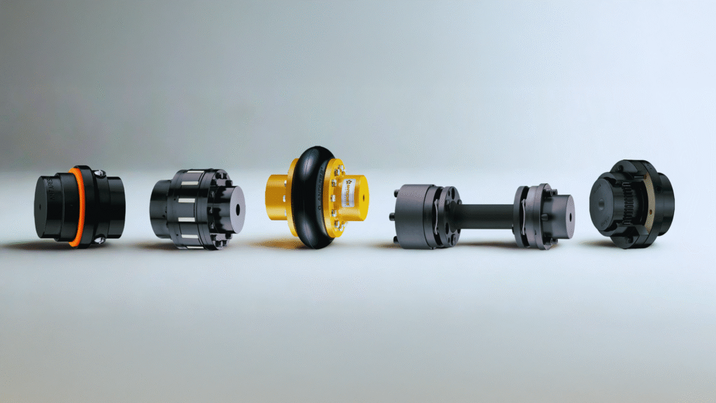
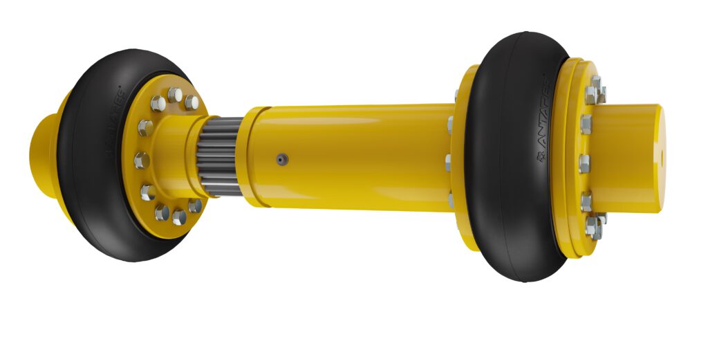
Flexible Couplings
The industry create Flexible couplings to handle misalignment, absorb shocks, and provide high vibration reduction capacity. The AT model features steel hubs and flanges, while the flexible element is made of rubber. This model sees use in a wide range of applications due to its versatility. In addition, they do not require lubrication.
Elastic Couplings
Elastic couplings, such as the H/HR and SW, use elastic elements (HTrans or polyurethane) to absorb misalignment and shocks. Thus, these couplings are excellent due to their ability to dampen vibrations and offer quiet performance. The H/HR coupling line works primarily in high-torque drives. The couplings are designed for use in the torque range supported by the coupling, which is 12,000 Nm to 1,340,000 Nm and shafts up to 600 mm in diameter.
Disc Couplings
Disc couplings use sets of thin metal discs that can flex to accommodate misalignment. They are suitable for high-precision applications and require torque transmission without backlash.
Chain Couplings
Chain couplings use a chain wrapped around two sprockets, allowing flexibility and, above all, the ability to handle misalignment. Therefore, they are ideal for low-speed and high-load applications.
Grid Couplings
Grid couplings have a metal grid that fits between two toothed halves. As a result, this grid allows for the absorption of shocks and vibrations, making them suitable for applications where these conditions are frequent. They are effective in protecting against torque peaks.
Jaw Couplings
Jaw couplings consist of two halves with teeth that fit into an intermediate elastic element. As such, they are capable of absorbing moderate shocks and misalignments, making them a common choice for small and medium-sized electric motors.
Fluid Couplings
Fluid couplings use a hydraulic fluid to transmit torque between the two halves. As such, they are excellent for applications that require smooth speed control and overload protection.
Magnetic Couplings
Magnetic couplings use magnetic force to transmit torque between the two halves without physical contact. Therefore, these couplings are ideal for environments that require hermetic sealing, such as submerged applications or applications with corrosive fluids.
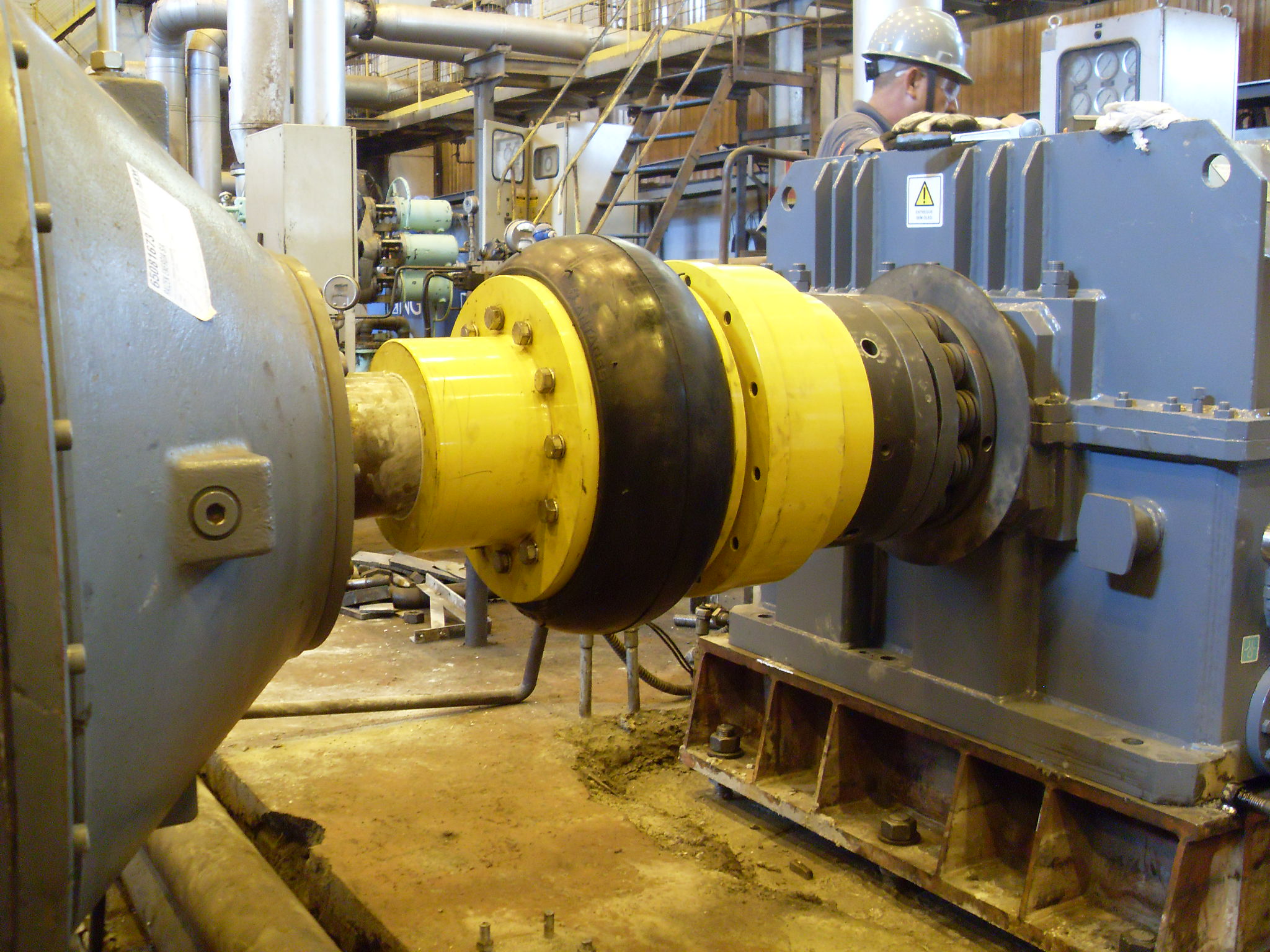
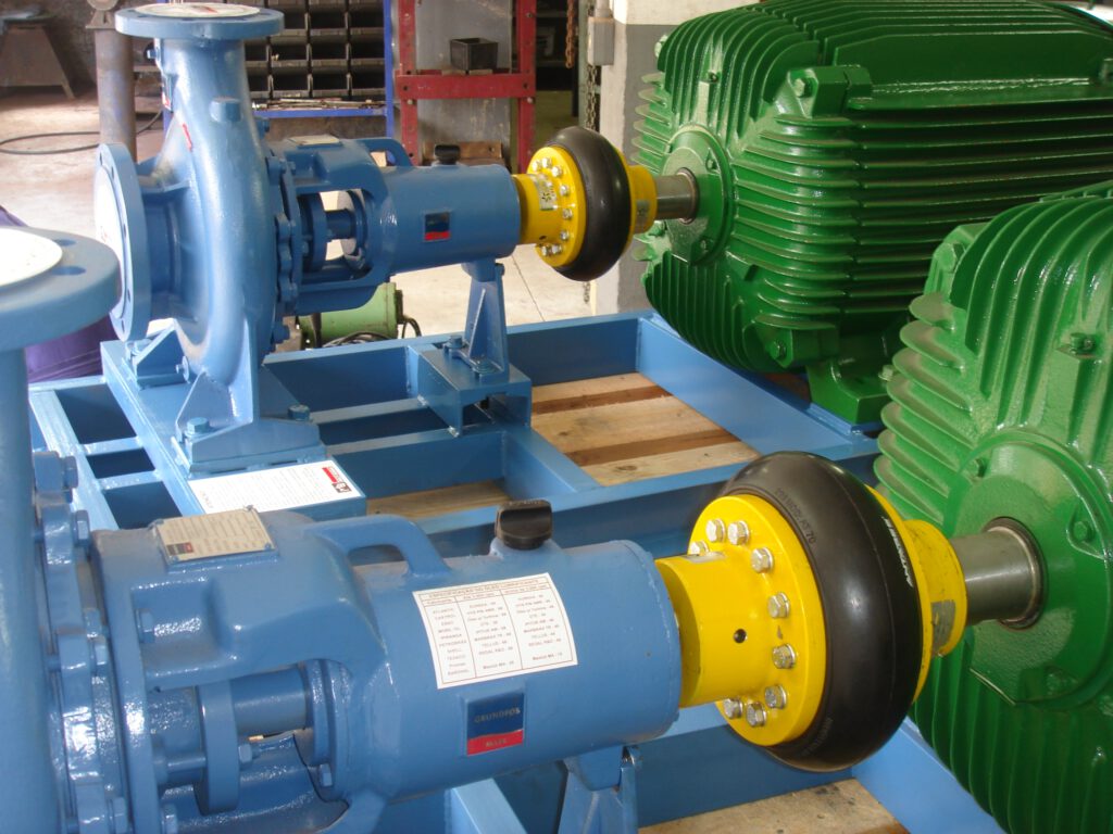
VLUU L100, M100 / Samsung L100, M100
Coupling on Belt Conveyors: Comparison and Selection
As previously mentioned, the selection of the appropriate coupling for belt conveyors depends on several factors, including:
- Torque Capacity: Must be compatible with the torque requirements of the application.
- Vibration and Shock Reduction: Important to protect sensitive components and extend the life of the system.
- Vibration Damping: The elastic elements of the AT coupling have a damping capacity that significantly reduces the vibrations transmitted between the motor and the reducer. Consequently, this is essential to prevent fatigue damage to the system components and to improve the life of the equipment.
- Shock Absorption: In applications where sudden load variations occur, such as when starting and stopping belt conveyors, the AT coupling protects the components by absorbing and dissipating mechanical shocks, preventing catastrophic damage.
- Misalignment Absorption Capacity: Varies according to the type of coupling and the misalignment tolerance of the application. Belt conveyors often face misalignments due to vibrations, mechanical wear and temperature variations. Therefore, the AT coupling absorbs axial, radial and angular misalignments.
- Axial Misalignment: The AT coupling can accommodate axial misalignments of up to 2-3 mm. This is therefore crucial to avoid unwanted axial forces that can damage bearings and other system components.
- Radial Misalignment: With a capacity to absorb radial misalignments of up to 0.5-1 mm, the AT coupling ensures that small variations in the relative position of the shafts do not result in operational failures.
- Angular Misalignment: The Antares AT flexible coupling can compensate for angular misalignments of up to 1-2 degrees, ensuring smooth and constant power transmission.
- Ease of Maintenance: Some couplings are easier to maintain and replace than others. In addition, the modular design of the AT coupling allows for simplified and efficient maintenance.
- Element Replacement: The team can replace the elastic elements of both H/HR, SW and AT flexible couplings without disassembling the entire coupling. This significantly reduces downtime and maintenance costs.
Important
- Visual Inspection: The design of AT couplings allows visual inspection of the elastic elements, facilitating early detection of wear or damage.
- Durability and Resistance: Antares selects the materials used in the manufacture of AT couplings to offer high resistance to wear and corrosion.
- High Performance Materials: The elastic elements of H/HR and SW, in Htrans or polyurethane, offer excellent resistance to abrasion, oils and chemicals. On the other hand, the metal components, usually in steel or cast iron, provide high mechanical resistance.
- Robust Design: The designers developed the AT coupling to operate in aggressive environments and under heavy loads, ensuring a long service life and reliable performance.
Application Versatility: AT couplings are adaptable to a wide range of configurations and torque requirements. - Torque Capacity: With torque capacities ranging from a few tens to thousands of Nm, AT couplings can be used in small and large industrial installations.
- Customizable Configurations: Engineers customize AT couplings to meet the specific needs of each application, including variations in size, material and type of elastic element.
- Operational Efficiency: Efficient power transmission is essential for belt conveyor systems.
- Minimizing Losses: The AT coupling design minimizes friction and misalignment losses, ensuring that most of the motor’s energy is transferred directly to the reducer.
- Improved Productivity: With smoother and more reliable operation, belt conveyors equipped with AT couplings have fewer maintenance downtimes, increasing productivity and reducing operating costs.
How Does a Belt Conveyor Work?
Belt conveyors are essential equipment in many industries, used to move materials from one point to another efficiently. Thus, simple mechanical and engineering principles underlie their operation, but engineers can implement them in a quite sophisticated manner, eventually depending on the specific needs of the application.
Basic Structure
Basically, a typical belt conveyor mainly contains the following main components:
- Conveyor Belt: The belt is the main element that moves the materials. Manufacturers can also make it of rubber, PVC, fabric, or metal, depending on the application and the type of material being transported.
- Support Structure: This is the metal structure that supports the belt and the conveyor components. Therefore, manufacturers usually make it of steel or aluminum.
- Support Rollers (Idlers): These are cylinders that support the belt and help keep it moving. There are loading rollers, which support the loaded belt, and return rollers, which support the empty belt on the return.
- Drive Unit: This consists of an electric motor, reducer and couplings that provide the force needed to move the belt.
- Drive Drum and Return Drum: The drums are large pulleys around which the belt is stretched. The motor connects to the drive drum and moves the belt, while the return drum maintains the belt tension on the opposite side.
- Tensioners: Systems that keep the belt correctly tensioned, consequently preventing slippage and ensuring smooth movement.
Operating Principle
In summary, we can divide the operation of a belt conveyor into several stages:
- Loading: At a loading point, workers or automatic feeders deposit the materials on the belt.
- Belt Movement: The electric motor drives the drive drum, which in turn moves the belt. The reducer then adjusts the speed and torque of the motor to meet the specific needs of the operation.
- Material Transport: As the belt moves, it transports the materials from one point to another. In other words: the support rollers ensure that the belt remains level and evenly loaded.
- Unloading: At the unloading point, workers or machines remove the materials from the belt. Consequently, gravity can perform this task, through chutes or automated unloading systems.
- Belt Return: After unloading, the belt returns to the loading point and passes over the return rollers and return drum. At the same time, scrapers clean the belt along the way to remove debris and ensure clean and efficient operation.
Suzana Facilito relacionamentos através das ações e ferramentas construídas a partir do marketing estratégico e digital.