Navegue em AT BP Bipartite Flexible Coupling:

FEATURES TECHNICAL TABLES
Foto produto
Foto produto
Foto produto
Foto Galeria
Foto Galeria
Foto Galeria

AT BP Bipartite Flexible Coupling

The AT BP Bipartite Flexible Coupling have a great ability to absorb misalignment, mechanical shocks and vibrations.

They allow the elastic center to be replaced easily, without moving it away from the equipment, even when the shaft ends are very close.

FEATURES

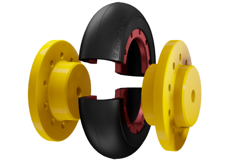
• Exclusive installation system in which tightening the screws guarantees the fixation of the elastic center
• Elastic element is fixed between hub and flange. Tightening the screws guarantees the resistance of the ELASTOMETER – METAL connection
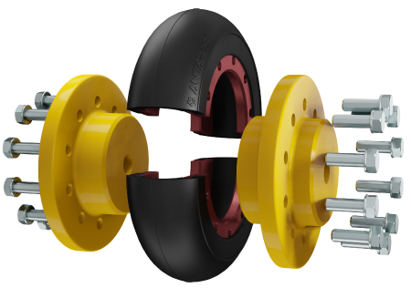
• The screws are fixed in the axial direction, that is, they are not positioned in the direction of rotation. Therefore, they are also not subject to detachment due to centrifugal force, a common problem in other two-part couplings.
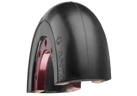
• Longer useful life, as the fixation of the elastomer with the metal is not subject to the action of aggressive environments or centrifugal force (acts in a direction perpendicular to the axis of rotation, moving material bodies away from it)
• Total safety, as the elastomer will not detach
• Greater torque capacity, making the product compact compared to other split couplings.

TECHNICAL TABLES

Model Nominal Torque (Nm) Conventional Nominal Torque (Nm) Line R Maximum Speed (rpm) Minimum Bore Maximum Bore CN (mm) Maximum Bore CI (mm) Weight (kg) Moment of Inertia CN (kgm²)
AT 25 BP 39 49 4000 9 24 26 1.03 0,000966
AT 35 BP 78 98 3800 9 32 38 2,75 0,003856
AT 50 BP 297 371 3600 20 48 57 5,75 0,01364
AT 70 BP 822 1028 3600 25 70 87 15,15 0,0596
AT 90 BP 1487 1859 2000 30 85 98 29,25 0,222
AT 105 BP 2187 2734 2000 35 110 116 42,20 0,317
AT140 BP 5950 7438 1890 40 145 158 74,3 0,966
AT 200/90 BP 17125 21406 1200 70 110 - 162,9 7,48
AT 200/140 BP 17125 21406 1200 80 150 240 175,4 8,44
AT 300/150 BP 58500 73125 700 100 160 310 284,8 9,46
AT 300/200 BP 58500 73125 700 100 220 310 328,3 9,56
Model and dimensions in mm D1 D2 S L1 L2 D5 D6 Standard Gap (distance between ends of axes) Alignment Tolerance AXIAL (mm) Alignment Tolerance RADIAL (mm) Screws Tightening Torque (kgf.m) INSTALLATION Screws Tightening Torque (kgf.m) AFTER 24H
AT 25 BP 74 36 30 63 30 95 66 3 -0,5 0,35 0,5 0,5
AT 35 BP 96 49 40 80 38,5 125 86 3 -0,75 0,5 0,75 1
AT 50 BP 127 66 50 103 50 165 120 3 0,65 1 2
AT 70 BP 169 93 65 143 70 220 150 3 -1,5 1 2 2,5
AT 90 BP 218 110 90 165 80 300 180 5 -2 1,2 5 6
AT 105 BP 235 140 90 205 100 335 200 5 -2 1,2 5 6
AT 140 BP 288,5 188 120 265 130 405 265 5 -3 2,4 6 7
AT 200/90 BP 436 150 185 297 128,5 550 - 40 -4 3,5 10 15
AT 200/140 BP 436 188 185 317 130 550 396 57 -4 3,5 10 15
AT 300/150 BP 535 225 235 411 175 730 490 61 -4 3,5 15 22
AT 300/200 BP 535 290 235 411 175 730 490 61 -4 3,5 15 22

Discover other products in the line